VLM Example: Share Screen in Real Time
This page explains how to setup a .vlm file that shares the screen in real time. We will do this by recording the screen and streaming it in the local network.
As a pre-requisite, refer to VLM Introduction to understand how to configure a simple .vlm file. Further, you may refer to Screen Record to get a deeper understanding of how screen recording is implemented in VLC.
Setting up the VLM File
For this example, we will stream the recording over UDP. To get a basic idea of how streaming over UDP works, refer to Stream over UDP.
In UDP streaming, we either need to specify the IP address of the receiving device, or we can stream to the multicast IP address (streaming to the multicast address simply means that the content will be pushed to all the devices in the local network).
We will cover both the scenarios.
Sharing screen in the Multicast Mode
In case you wish to stream to multiple receivers or you don’t know the IP address of the receiver, you can use the following vlm code:
new screen_share broadcast enabled
setup screen_share input "screen://"
setup screen_share output #transcode{vcodec=mpgv}:udp{mux=ts,dst=239.255.255.250:8090,sap,name=testing}
setup screen_share option sout-keep
setup screen_share option screen-fps=100
setup screen_share option file-caching=1000
control screen_share play
For the above code:
Create a new file in any text editor and copy the code.
Save the file with the
.vlmexension (likeshare.vlm)
Start screen sharing
Now, execute the vlm file by running the following code in the terminal (on the device whose screen you want to share):
$ vlc --vlm-conf=share.vlm
Running the above code will start the recording and streaming.
Receive the screen-recording stream
To receive the recording, simply open the VLC Media Player on the receiving device(s) and follow these steps:
Navigate to View -> Playlist
Click on
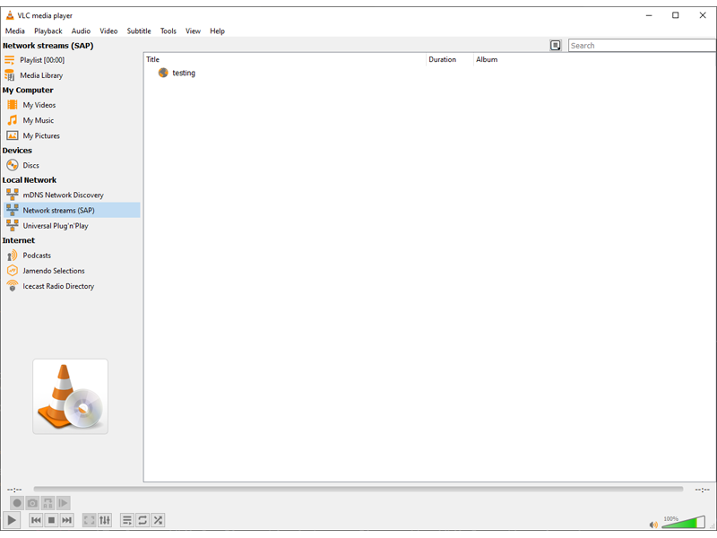
Network Streams (SAP)which is in theLocal Networksection on the left side.You will see a SAP stream by the name
testing, like in the figure below.Double click on it to begin receiving.

How the stream looks like in the VLC window.
In this case, the recording is pushed to all the devices (including the idle ones), as illustrated by the diagram below:
Sharing screen in the Unicast Mode
In case you wish to share the screen to only one device, it might be better to stream it in the unicast mode.
For unicast streaming, we will modify the IP address in the dst parameter in the third line of the same VLM file. Assuming that the IP address of the receiving device is 192.168.0.102 (replace this with the IP address of the receiving device in your local network), the VLM file would look like:
new screen_share broadcast enabled
setup screen_share input "screen://"
setup screen_share output #transcode{vcodec=mpgv}:udp{mux=ts,dst=192.168.0.102:8090,sap,name=streaming}
setup screen_share option sout-keep
setup screen_share option screen-fps=100
setup screen_share option file-caching=1000
control screen_share play
Rest of the steps (for execulting the vlm file and receiving the stream) remain the same.
Following is how a simplified version of the network might look like: